
- View Products
- Blasting pots
- Blasting cabinets
- Suction blasting cabinets
- Pressure blasting cabinets
- Blasting machine with rotary basket
- Turntable blasting machine
- Throughput blasting machine
- Roller conveyor blasting machine
- Internal blasting machine
- Multi-nozzle blasting machine
- Satellite table machine
- Blasting installation with sliding door
- Robotic blasting machine
- Precision spotblaster
- Shot blasting room
- Shot blasting container
- Automated shot peening machines
- shot blasting equipment
- wheelblasting machines
- Spinner hanger
- Tumble belt shot blasting machine
- Rotary table blast machine
- Roller conveyor wheelblasting machine
- Overhead monorail conveyor shot blasting machine
- Turn table
- Bogie table work car shot blasting machine
- Continuous tumblast machine
- preservation line
- Stone and brick shot blasting machine
- Anchor chain shot blasting machine
- Steel pipe shot blasting machine
- Gas cylinder shot blasting machine
- Drum type wheelblasting machine
- Mobile concrete floor shot blasters
- Wire mesh conveyor wheelblasting machine
- gas cylinder shot blasting machine
- disa blasting wheels
- Blasting media
- wheelblasting machines
- Blasting media
- Dust collectors
- Blasting with compressed air
- References
- Blasting Knowledge
- Internal Pipe Shot Peening System
- Gas cylinder inside blasting machine
Need advice?
Need expert advice? Reach out via call or WhatsApp for immediate support.
- (86)-0532-88136558
- (86)-13589238091
- disa@disachina.com
Get in touch
Leave your details below and one of our specialists will be in touch as soon as possible.
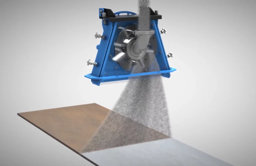
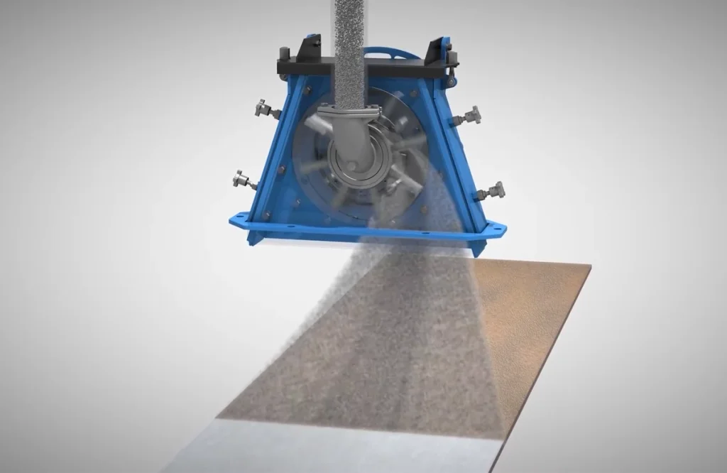
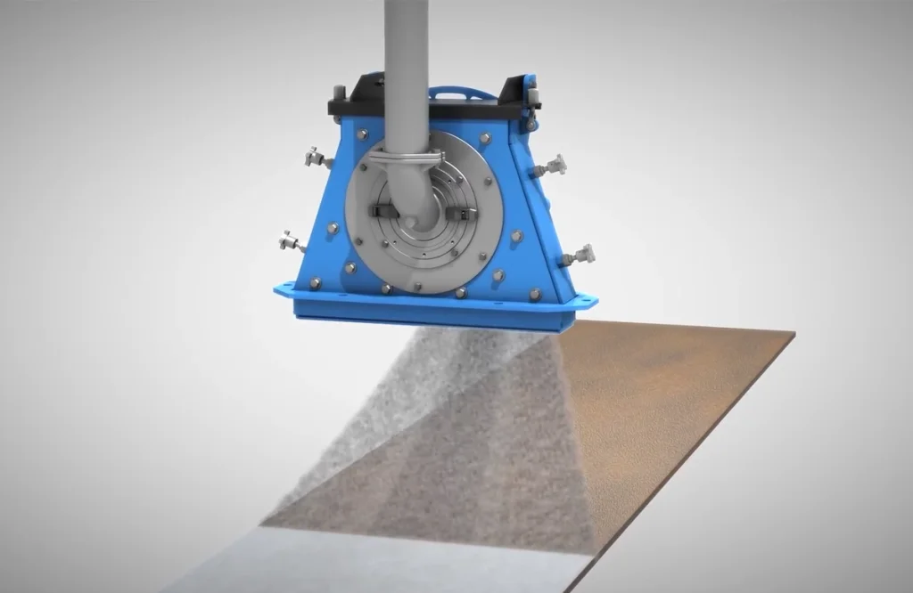
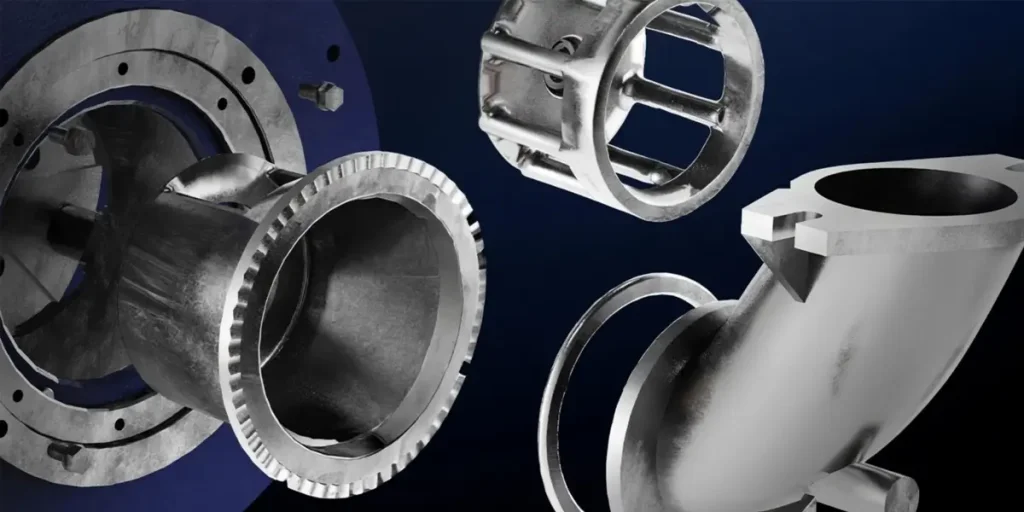
disa blast WHEEL: OPTIMAL EFFICIENCY & EFFECTIVENESS
Disa blast wheels are renowned for its high capacity and energy efficiency. The blast wheels come in various power ratings for a high degree of flexi-bility. Highly wear resistant material ensures maximum service life.
Disa presents three robust blast wheel models, engineered for superior performance, durability, and efficiency. Constructed with premium materials and cutting-edge technology, our blast wheels are designed to maximize productivity while minimizing operational costs. Each model delivers distinct advantages tailored to diverse blasting applications, ensuring consistent, high-quality results across various industrie
Why choose Disa?
- Blades are through-hardened to 62–65 HRC from surface to core for exceptional wear resistance.
- Blades is delivered pre-packaged and dynamically balanced, with a maximum weight difference of ±5.0 grams between blades in the same set.
- High-performance blasting turbine with robust manganese steel housing for superior strength and durability.
- Direct Drive Blast Wheels Assures maximum energy is optimally used at all times.
- Over 30 years of experience in the blasting technique

- High shot-blasting throughput, uniform coverage, and low energy consumption.
- High-chromium alloy blades combined with manganese steel guard plates for exceptional durability.
- Easy Maintenance: Modular design with top access cover and red grease fitting for quick and convenient servicing.
- Designed for direct replacement or seamless upgrade of older shot blasting machines.

- Smooth Operation: Smooth start-up, low energy consumption, low noise, and extended service life.
- Superior Durability: High-chromium alloy blades and wear-resistant guard plates for uniform shot projection, convenient maintenance, and extended service life.
- High Efficiency: Large shot-blasting capacity, uniform coverage, and low energy consumption.

- High Efficiency: Large shot-blasting capacity, uniform hot spots, excellent cleaning performance, and low energy consumption.
- Superior Durability: Blades hardened to 62–65 HRC, delivering service life far exceeding that of ordinary shot blasters.
- Easy Maintenance: Modular design enables quick replacement of blades and control cages.
- Control cabinet with PLC control
DISA BLAST WHEEL: Leading Durability High efficiency
The shot blasting turbine components are the core of every Disa shot blasting equipment. During the shot blasting operation, the metered abrasive flow continuously flows into the impeller that rotates synchronously with the shot blasting turbine through the inlet. The abrasive accelerates within the impeller and is smoothly guided onto each blade through a slot on the distributor wheel. This method ensures the optimal energy utilization rate of the drive motor. Each shot blasting turbine on the Disa shot blasting equipment is equipped with an independent abrasive valve, which can precisely control the abrasive flow rate to each shot blasting turbine. The abrasive flow is initiated only when the abrasive reaches the shot blasting turbine, thus minimizing the equipment damage caused by idling.
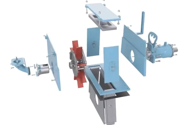
High efficiency and optimization of the abrasive flow
The symmetrical sandwich construction (double side panes) of the DISAA Wheel ensures an efficient and even flow of blasting media within the blast wheel. Conventional blasting wheels lose power due to the turbulence of the abrasive inside the turbine. The revolutionary throwing blade mount of the DISA wheel, which at the same time takes on the task of connecting webs, avoids these performance-reducing blasting media turbulence. The innovative design of the DISA Wheel guarantees a 7 times better flow of blasting media, 5% higher energy efficiency and 3 times longer service life of the side windows compared to all other turbines available on the market.
DISA Advanced Turbine Technology
To be effective, the blast media must be accelerated to very high speeds. DISA achieves this by constantly improving the turbine technology, especially the throwing blades, which are key to achieving the required media throwing speeds. The centrifugal force of the turbine accelerates the blast media to the required throwing speed. Compared to air blast systems, turbines require a relatively low energy input and provide a very high level of energy efficiency. The turbine is the heart of any shot blasting equipment. It is the element responsible for the continuous projection of the abrasive material being used and must therefore have a series of features that guarantee its performance and durability over time. DISA turbines allow the impact velocity and shot flow-rate to be adjusted, achieving different finishes without the need to change the type of abrasive.
Extremely easy to maintain
High performance due to their advanced design that obtains an excellent ratio between motor power and blasted shot.
Fast and easy maintenance, because the parts are accessible and extremely easy to assemble and disassemble.
Delivery program
Multipurpose protection components that adapt to several positions and therefore ensure maintenance with fewer parts.
High abrasion resistance, proven by the constant research we perform on new materials to improve unit performance and profitability.
The possibility of automatic orientation of the blast beam, even during the cleaning cycle.
disa turbines can vary impact velocity and blast flow to obtain different finishes without the need to change the type of abrasive material.
Blast wheel retrofitting
Retrofitting of the existing blower wheel systems with the new DISA wheel is possible without any problems. Please turn to our staff in confidence.
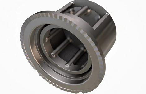
Blade Life and Inspection Guidelines
Blade lifespan is primarily determined by the specific cleaning application and operational factors, such as proper separator settings. However, life expectancy varies dramatically depending on the presence of sand; blades wear significantly faster in sand-heavy applications (e.g., foundries) compared to sand-free environments.
When to Replace Blades
Blades must be replaced when they exhibit deep grooves, chips, or breakage. While severe blade damage can cause abnormal wheel vibration, vibration should not be the primary indicator for replacement, as substantial damage often occurs before it becomes noticeable.
Instead, rely on a strict inspection schedule:
Sand applications: Inspect every 24 blast hours.
Non-sand applications: Inspect every 200 blast hours.
Any blade worn halfway through, chipped, or broken must be replaced immediately. Delaying replacement can lead to accelerated wear on adjacent blades, holes in the wheel, or bearing failure caused by severe vibration.
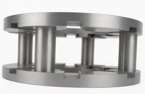
Blade Retention System
DISA blast wheel blades feature a dovetail-shaped design that slides into corresponding grooves in the wheel. They are secured radially outward by a centering plate and locked radially inward by a permanent "Stop" within each groove during rotation.
Blade Replacement Procedure
Replacing the blades is a straightforward process:
Remove the feed spout, impeller, control cage, and centering plate.
Remove the housing cover and top liner to expose the blades.
Gently tap each blade toward the center of the wheel until it releases from its groove.
Hold the blade by hand and extract it through the opening previously occupied by the control cage and impeller.
Both components experience edge wear depending on the wheel's direction of rotation. They must be replaced before the edges wear back more than 3/16". Exceeding this limit can cause significant secondary damage:
Control Cage: Excessive wear shifts the blast pattern. If severe, this not only reduces cleaning speed but also causes abrasive to strike and damage liners and other vulnerable internal parts.
Impeller: Over-worn impellers cause the abrasive to miss the leading edge of the blades. This disrupts the proper flow of abrasive, reducing cleaning efficiency and accelerating wear on the wheel housing.
Replacing these components is a straightforward process that requires only a specialized elongated Allen wrench, commonly referred to as an "impeller wrench." The steps are as follows:
Remove the feed spout.
Remove the control cage clamping lugs.
Use the impeller wrench to remove the impeller bolt.
Once the bolt is removed, both the control cage and the impeller can be easily extracted.
The interlocking wheel liners in a DISA blast wheel are designed for easy removal. To replace them, simply remove the top cover and top liner, then slide out the end liners from each end. Note that the end liners are secured in place by locking bolts located on the exterior of the wheel housing.
During inspection, it is critical to ensure the liners never wear to the point of developing holes. Additionally, if you notice that one set of end liners is wearing significantly faster than the opposite set, it is usually an indication that the control cage setting is incorrect and requires adjustment.
There is a significant entanglement hazard from the moving buckets while the elevator is in operation. To prevent injury, all access points—including maintenance guards, inspection covers, and the elevator's top cover—must be closed and securely fastened with bolts before operating the shot blasting machine.
1. Mechanical Hazard: The rotating magnetic drum presents a serious risk of entanglement and physical injury. Never place hands or any body parts near the drum while it is in operation.
2. Magnetic Field Hazard: The magnetic drum generates a powerful magnetic field, which is life-threatening for individuals with pacemakers. Personnel with such medical devices are strictly forbidden from approaching the magnetic separator and must maintain a safe distance at all times.
The hook-type shot blasting machine ensures uniform surface cleaning and strengthening through the following processes:
1. Workpiece Suspension & Rotation
Workpieces are hung on a hook trolley driven by a three-phase gear motor. Inside the chamber, the hook employs a bidirectional swinging and rotating motion, ensuring even exposure to the shot flow. The shot blasting head speed (1500-3200 RPM) is adjustable via a frequency converter to suit various workpieces.
2. High-Speed Shot Blasting
Driven by a Siemens motor, the direct-drive impeller (φ380 mm) features 8 high-chromium alloy blades (55 HRC). Abrasive shots are accelerated and impact the workpiece at speeds up to 73 m/s, with coverage intensity precisely controlled by the head's rotation speed.
3. Shot Recycling & Separation
Used shots and debris are transported via a bottom screw conveyor and bucket elevator (manganese steel buckets) to an air separation system. Impurities are removed through gravitational and magnetic separation, while clean shots are recycled into the hopper.
4. Dust Treatment
A two-stage filtration system ensures clean air discharge:
Primary cyclone separator: Removes large particles.
High-efficiency bag filter: Captures micron-sized dust (>99% efficiency).
Purified air is discharged via a negative pressure system (38,000 m³/h), with noise controlled at ≤85 dB(A).
5. Automation & Safety
PLC Control: Manages blasting time, head speed, and hook movement.
Safety Interlocks: Pneumatic doors automatically lock during operation.
Protection: Equipped with emergency stop buttons and vibration monitoring to prevent overloading.